The Anderson's Rotary Spreader Model 2000 SR

The Anderson\'s Rotary Spreader Model 2000 SR
Price/Ea.
$1,060.95

Have a Question? Ask Our Pros!

Email Our Pros
We're here to help
Offline. Leave Us a Message

You May Also Need

Average Rating

There are no reviews for this product yet. Be the first.

Product Overview

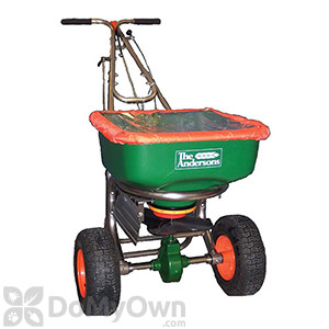
The Anderson’s Rotary Spreader Model 2000 SR is a sturdy rotary spreader with a stainless steel frame and pneumatic tires.  It features a unique helical cone-adjust spread pattern for improved accuracy. The durable stainless steel frame provides stability and will not rust.  This spreader comes with a hopper cover and right side deflector shield.  Ideal for applying granular fertilizers or pesticides, ice melt, sand, or grass seed. 

Product Documents

Features and Specs

For use in Applying granular fertilizer and pesticides, grass seed, sand and ice melt.
Material / Construction Stainless steel.
Special Features Features patented helical cone for more accurate spread pattern.
Shipping Weight 47.00 lbs
Manufacturer The Andersons (Mfg. Number: ASP8091)
UPC 031865306501

Details

You will need the following tools:

  • 1/2 inch, 7/16 inches and 3/8 inches open-end wrenches (or adjustable wrench)
  • Pliers
  • Phillips head screwdriver
  • Grease gun

Assembly

  1. Turn the spreader upside-down. Place the wheels on the axle with the longer portion of the hubs facing inward. Secure the drive wheel “A” (right side) to the axle using the 3/16” cotter pin. Attach the idler wheel “B” (left side) to the axle. Then insert the 1/8” cotter pin through the axle and secure. Please note, both wheels are identical and can be used on either side.
  2. Place the spreader on its front side and attach the rest to the frame using (4) 1/4-20 x 2-1/2” Phillips screws and locknuts.
  3. Return the spreader upright position and attach the upper handle to the rest with (4) 1/4-20 x 1- 1/2” carriage bolts and locknuts. Be sure that the handle lever is facing up.
  4. Insert the bent end of the main shutoff connecting rod through the hole in the lever and secure with a 3/32” cotter pin.
  5. Thread one 5/16-18 hex nut onto the lower end of the main shutoff control rod until it stops. Insert the rod through the pivot lever arm as shown, and thread the second 5/16-18 nut up to the pivot lever arm; do not tighten.
  6. Pull the main shutoff lever to the closed position and look inside to see if the portholes are closed. If not, adjust the top and bottom nut down in small increments and recheck for closure. CAUTION-DO NOT ADJUST THE TOP NUT TOO FAR DOWN TO PREVENT BINDING THE MECHANISM. When the ports are closed completely, thread the bottom nut up and tighten both nuts.
  7. Attach the auxiliary shutoff bracket to the left side of the handle using (2) #10-24 x 1 1/4” Phillips screws and locknuts. Slide the push-pull control into the notch on the bracket between the washer and the hex nut. Tighten the nut while taking care not to twist the cable. Secure cable to frame with a wire tie.
  8. Attach the lever bracket to handle using (2) #10-24 x 1 1/4” Phillips screws and locknuts. Be sure bracket is aligned as shown. Slide the spring onto the end of the deflector rod with the form tabs as shown. Insert the end of the rod through the hole in the deflector bracket. Slide the rubber cap onto the end of the rod. Note: rotate the deflector rod to the up position (lever is up)
  9. Insert the opposite end of the deflector control rod into the loop end of the deflector shield assembly. Secure lower end of control rod with a hitch pin. Test control rod by rotating the rod–the deflector shield should rotate up and down.
  10. Using a grease gun, lubricate the grease fittings on the axle bearing housings and gear carrier. Do not overfill. Apply a small amount of grease to the gear teeth. Install the two gearbox cover halves and secure with the three retainer clips. Insert the screen inside the hopper and secure it with the factory installed clips.

Operation

  1. Check product bag for rate setting (letter), cone setting (number), and swath width. The rate-setting is achieved by loosening the rate control knob and sliding the rate control plate until the pointer aligns with the desired letter. The cone setting is used to control the spread pattern left and right and is adjusted by rotating the index tab on the orange helical cone to the desired number.
  2. Pull the main shutoff lever to the closed position before filling the hopper.
  3. Start rolling the spreader forward before opening the shutoff lever; close shutoff lever before stopping.
  4. Hold the handle so the hopper is level. Tipping the spreader to far forward or backward will cause uneven spreading.
  5. Use the swath width recommended on the bag for your model and push the spreader at 3 MPH (a brisk walking pace). Apply material in the forward direction only-not while pulling.
  6. The settings given on the product label are recommended starting points. Test rate and pattern in a small area before treating a large area. Actual application rate can vary depending on the weather, spreader condition, and walking speed.
  7. The deflector shield is used to block off the right side portion of the swath width. It should be used in the “ON” position (shield is down) together with the auxiliary shutoff in the “CLOSED” position (done by pushing the control knob forward). IMPORTANT: Turf products will be applied excessively at the center of the swath if the auxiliary shutoff is not closed when the deflector is in use. Always remember to re-open the auxiliary shutoff (pull the control knob back) when returning to a full swath width.
  8. A hopper cover is provided with your new spreader. Use it to protect turf products inside the hopper from light rain or windy conditions during transportation.

There are no reviews for this product yet. Be the first.

Questions & Answers

Have a question about this product?

There are no questions for this product yet. Ask the first.